
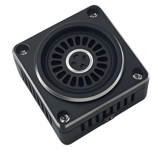
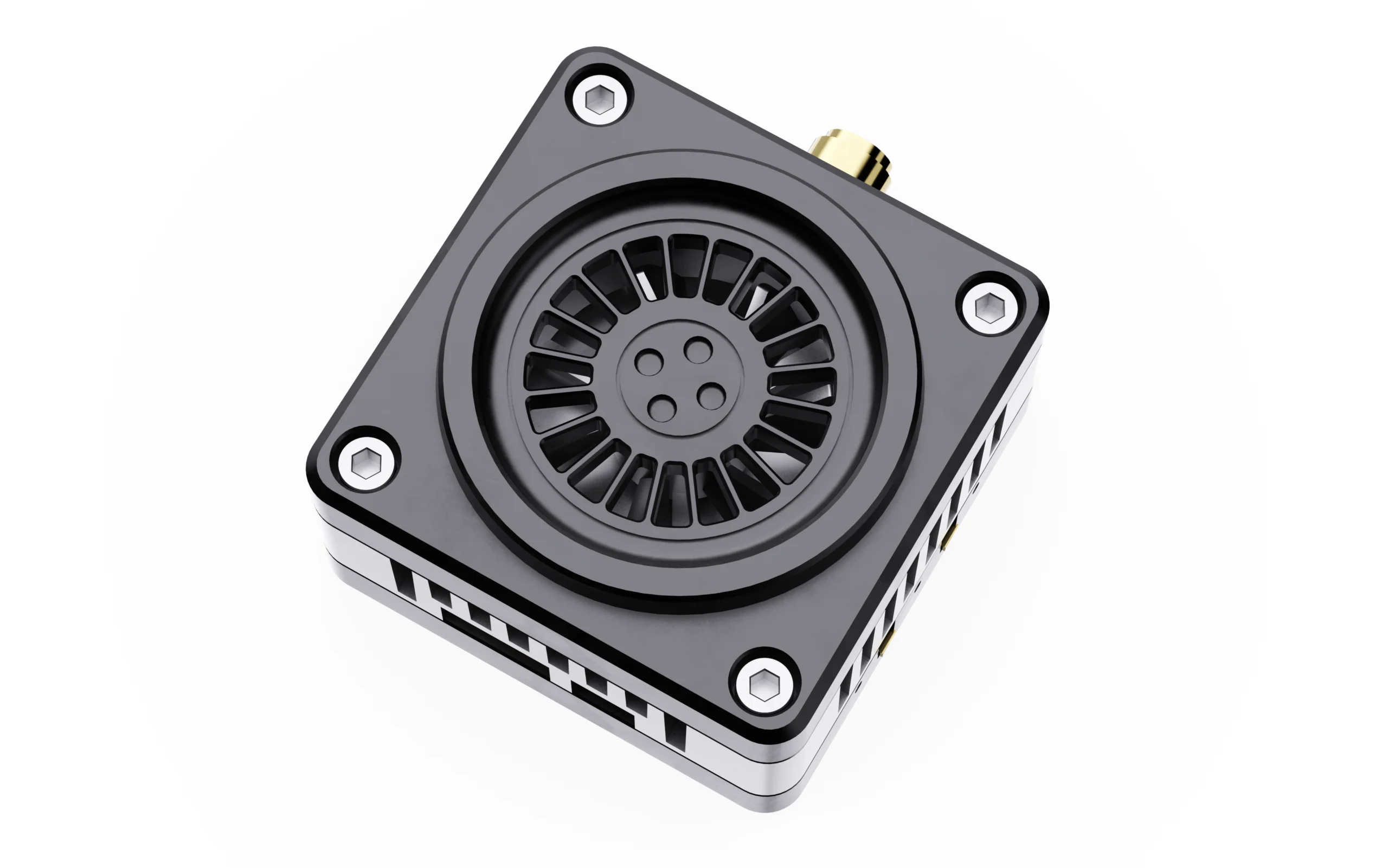
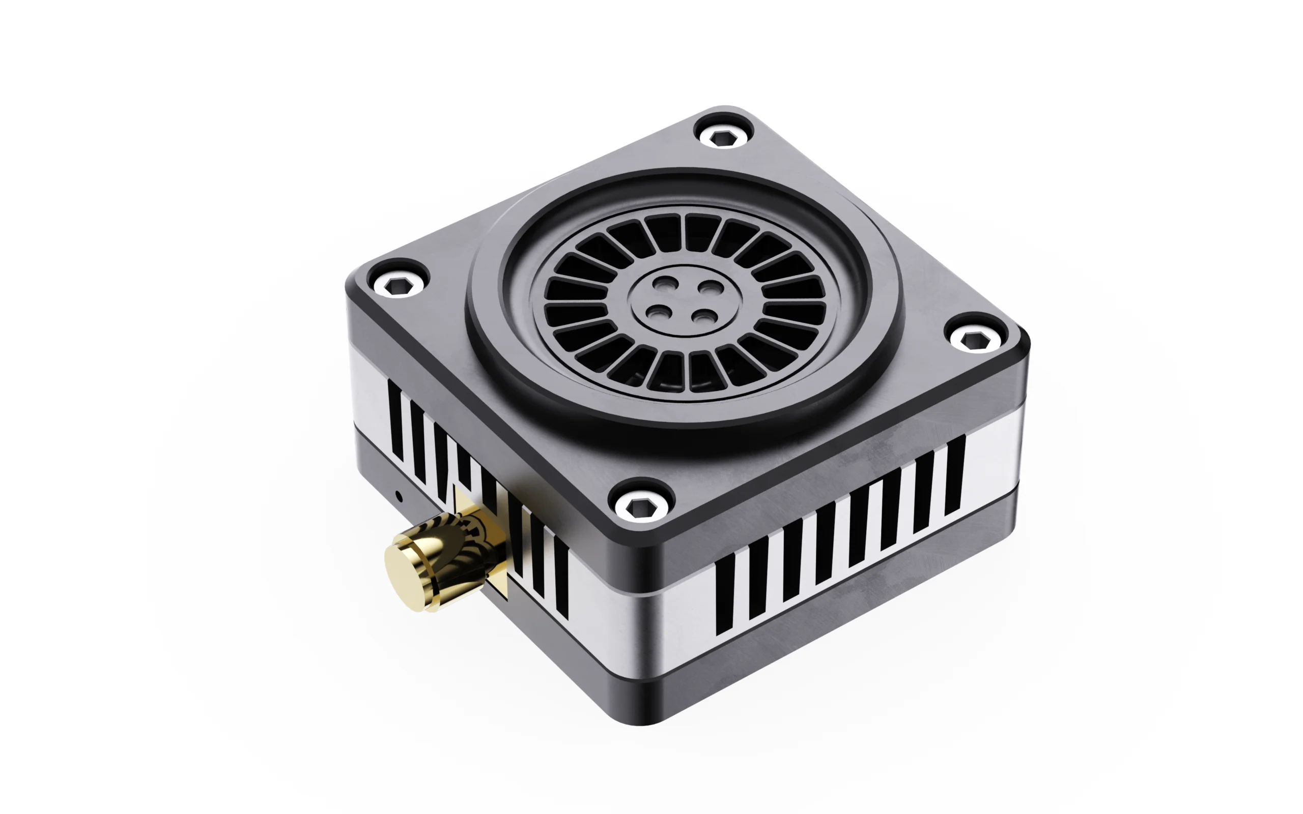
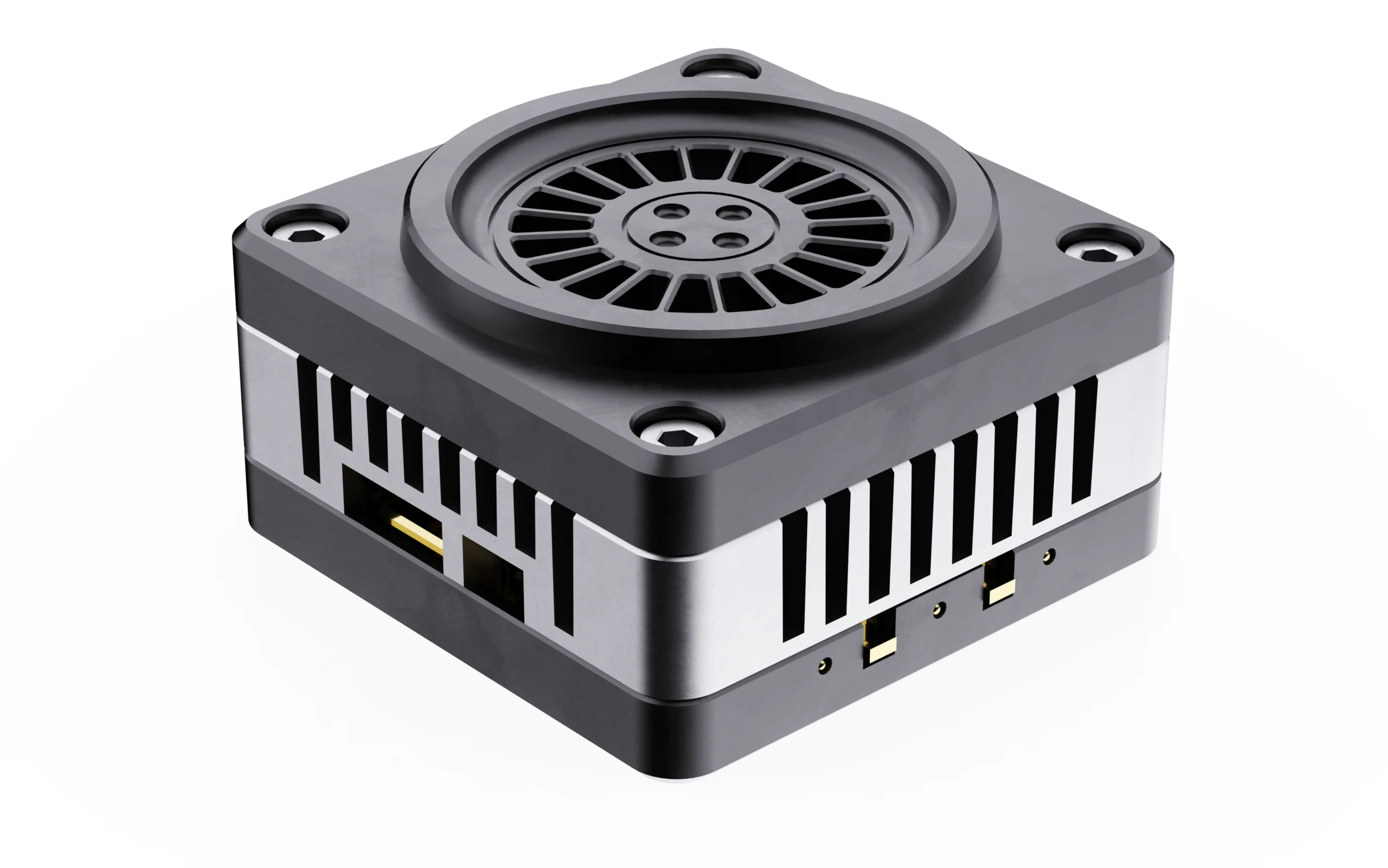
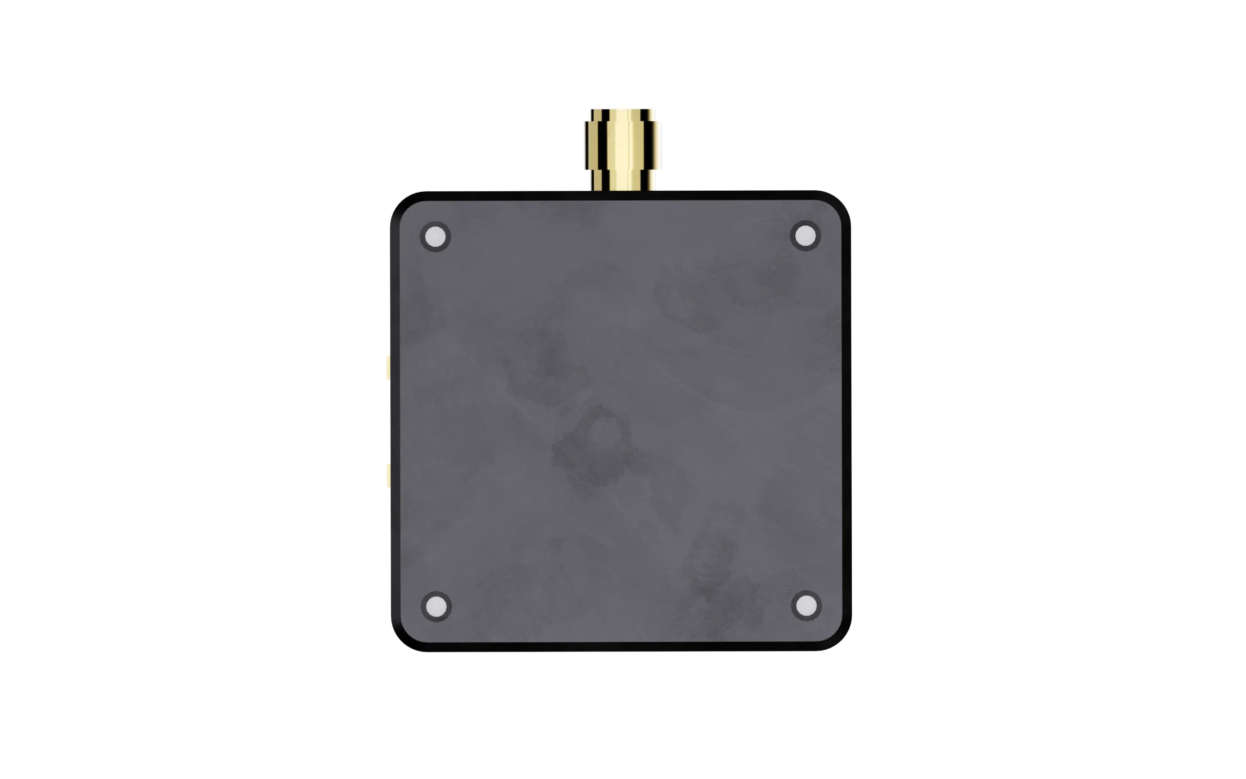
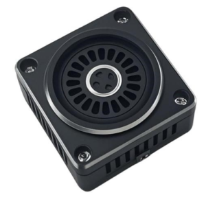
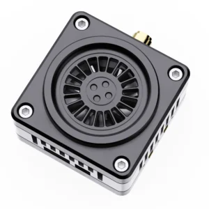
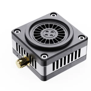
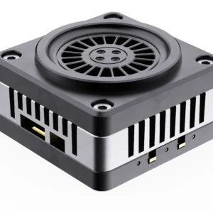
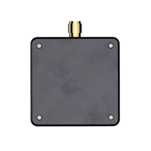
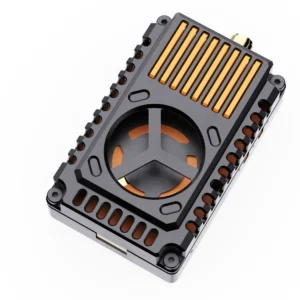
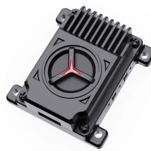
Product Appearance
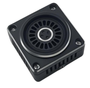
Product Dimension
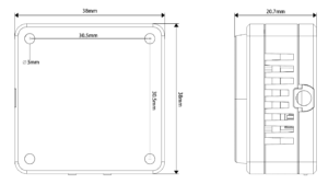
Function Introduction
1. Channel indicator: Red LED
2. Band indicator: Blue LED
3. Power indicator: Green LED
4. Band & Channel changer button
5. Power changer button
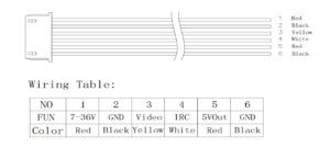
6. 1.0 6P Power connector
7. Cooling Fan Power Cable Holder
8. MCXantenna connector
Control Method and LED Indicator
1. Button ④ is used to switch band and channel; every time when button ④ispressed for a short time to switch to the next channel, the red LED ①will flash, 1.2.3.4.5.6.7.8.9 in turn. The operation can be cyclic; see the following diagram for details!
| Short press button ④ to switch channel | ||||||||
| Red LED | CH1 | CH2 | CH3 | CH4 | CH5 | CH6 | CH7 | CH8 |
| Flash once | Flash twice | Flash for 3 times | Flash for 4 times | Flash for 5 times | Flash for 6 time | Flash for 7 times | Flash for 8 times | |
2. Long press button ④ to switch frequency band, long press for 5 seconds the corresponding blue LED will flash, in order of frequency group A.B. This operation can be cyclic; see the following figure for details!
| Press and hold button ④ to switch channels | ||
| Blue LED | Band A | Band B |
| Flash once | Flash Twice | |
3. Button ⑤ is the power adjustment button, each short press switches the power by one step, cycling between the two steps of 25mW and 5000mW.The green LED is the power indicator, the status is shown in the following figure, 25mW blinks once, 5000mW blinks twice. Press and hold for 3 seconds to enter pit mode, the green light is always on. See the figure below for details!
| Short press button ⑤ Power switch | |||
| Green LED | Pit Mode | 25mW | 5000mW |
| Everlasting brightness | Flashes 1 time | Flashes Twice | |
Note
This VTX has a temperature protection function, when the temperature of the microphone is higher than 100 ℃, the transmitter power of this microphone will be reduced by one step, if the temperature is still higher than 100 ℃ continue to reduce the power by one step until the lowest power (25mW); at this time, the microphone temperature will be lowered, and when the temperature is lowered to 95 ℃, the transmitter power will be returned to the originally set power level.
Frequency Table
| Channel | 1 | 2 | 3 | 4 | 5 | 6 | 7 | 8 | |
| BAND A | 3330 | 3350 | 3370 | 3390 | 3410 | 3430 | 3450 | 3470 | MHz |
| BAND B | 3170 | 3190 | 3210 | 3230 | 3250 | 3270 | 3290 | 3310 | MHz |
Illustrate of 6P 1.0 Wiring
Notice for Use
1. The VTX must be installed with space to ensure that the air convection around the module to ensure that the module heat dissipation; otherwise, the module overheating protection start, reduce the power to transmit, or even shut down the power to transmit.
2. It is recommended that before turning on the power, to ensure that the correct voltage range, positive and negative poles are correct, so as not to burn components.
3. It is recommended that before turning on the power, make sure that the RF RF output has been installed antenna, which can extend the life of the module.
4. Please read the instruction manual before use, so that you can correctly wire and extend the module service life.
Legal Disclaimer
Important Notice on Radio Frequency Usage
1.DMKR high-performance VTX modules (3W-7W) are powerful RF instruments.Designed for specialized industrial, research, and laboratory applications. By purchasing this product, the buyer acknowledges and agrees to the following:
2.Regulatory Compliance: It is the buyer’s sole responsibility to ensure that the operation of this device complies with local laws, radio frequency regulations, and licensing requirements in their respective country or region.
3.Professional Use Only: This equipment should only be operated by qualified professionals. DMKR is not liable for any legal consequences, fines, or damages resulting from illegal or improper use.
4.Frequency Licensing: The 7.2GHz band may be restricted or require a specific technician’s license for operation. Please consult your local telecommunications authority (e.g., FCC, OFCOM, BNetzA) before powering on the device.
5.Risk of Misuse: The user assumes all risks associated with the deployment of this hardware. DMKR does not authorize the use of these devices in prohibited areas, including but not limited to, near airports or restricted government airspace.
6.No Liability: In no event shall DMKR be held liable for any direct, indirect, or incidental damages, including hardware failure of the UAV/UGV or legal intervention, arising out of the use or inability to use this product.
7.Safety Warning: High-power RF devices generate significant heat and radiation. Ensure proper thermal management and maintain a safe distance during operation.
8.Hardware Modification: Unauthorized modification of the firmware or hardware may void compliance certifications and safety protections.

Reviews
There are no reviews yet.